Flight Control Board
3 Şubat 2023

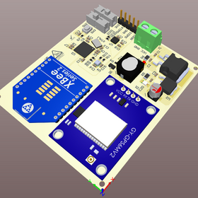
The project includes the design process of a circuit and board that perform as the flight computer of a medium altitude rocket.
The Flight Control Card is designed to fulfill the most basic and critical functions for the flight process of the rocket to which it is connected.
These critical tasks are:
Being able to read and process data from sensors without any problems.
To be able to send data from sensors to the Ground Support Station.
Calculating real-time location data and sending it to the Ground Support Station.
To deliver the Mission Payload to the targeted area by detonating at the appropriate position and altitude.
STM32F401CCU6 card was used as the processor. The criteria for choosing this processor are the high number of SPI, I2C, UART and GPIO pins on it and the fact that it is not large and does not take up much space. In addition to its basic criteria, the fact that it can operate at a frequency of up to 84 MHz also brings the advantage of high data processing of this processor.
The circuit receives its power energy from 4 3.7V Li-Po batteries. This energy must be distributed to the elements in the circuit in a controlled manner. For this purpose, there are 5V and 3.3V reducing linear regulators on the circuit. By using these regulators, voltage fluctuations that may occur in the circuit are eliminated and pure DC energy is transmitted to the units on the circuit.
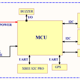
BME280, one of the sensors on this board; It calculates temperature, barometric pressure and humidity data and transmits them to the processor. Data flow was provided using the I2C communication protocol with the BME280 sensor processor. The data obtained from this sensor is used to obtain the altitude data of the rocket.
The electronic card contains gyroscope, accelerometer and compass/magnetometer units that can make measurements in 3 axes in the 10-DOF IMU (MPU 9255) sensor module. Data flow was provided using the I2C communication protocol with the 10-DOF IMU sensor processor. Using these units, yaw, pitch and roll angle as well as the rocket's speed are calculated.
After completing its mission, the landing location is calculated with the data obtained from the GPS module on it.
Telemetry data is sent to the Ground Support Station via the XBEE S2B Pro module. Data flow was provided using the UART communication protocol with the XBEE S2B Pro Module and GPS Module processor.
Thus, many parameter data are obtained during the mission process, which starts from the rocket's takeoff ramp and continues until it lands.
All electronic components used in the project are as follows:
STM32F401
4 x 3.7V Li-Po Batteries
LM2940 Regulator
LD1117 Regulator
BME280
MPU9255 (10 DOF IMU Sensor)
GY-NEO6MV2 (GPS Module)
XBEE S2C PRO
5V Buzzer


