I2C Shield
2 Ekim 2024

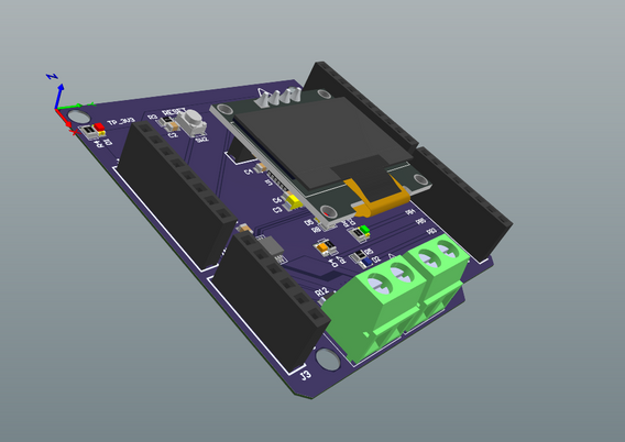
The project includes the design of a circuit that can work compatible with the NUCLEO-F411RE board and includes various sensors and peripherals.
The I2C Shield board is designed to be compatible with the NUCLEO-F411RE board and is capable of performing tasks involving sensors and various peripherals.
These critical tasks include:
- Seamlessly reading and processing data from sensors.
- Sending sensor data to the NUCLEO-F411RE board microcontroller.
- Activating the OLED display, LTC2990, ADXL345, and user LEDs and buttons for the user.
Power and data from the sensors and peripherals are transmitted via headers conveniently placed on the NUCLEO-F411RE board.
The circuit receives its power directly from the NUCLEO-F411RE board.
One of the sensors on this board, the ADXL345, can measure acceleration values in real time along three axes (X, Y, Z). Data flow is provided by the ADXL345 sensor processor using the I2C communication protocol. Data obtained from this sensor can be measured digitally in the X, Y, and Z axes with forces of ± 2G, ± 4G, ± 8G, and ± 16G. Address pins are set to GND. The I2C address is 0x53h.
The LTC2990 Temperature, Voltage, and Current Monitor Sensor includes temperature, voltage, and current measurement units. Data flow is provided by the LTC2990 sensor processor using the I2C communication protocol. The LTC2990 is used to monitor system temperatures, voltages, and currents. Through the I2C serial interface, the device can be configured to measure many combinations of internal temperature, remote temperature, remote voltage, remote current, and internal VCC. The LTC2990 address pins (ADDR0 and ADDR1) are set to GND. The I2C address is 0x98h.
The OLED display connections are implemented using headers, and the I2C communication protocol is implemented.
The circuit includes a Reset button for manual reset, a customized user button, and four user LED circuits.
Since the sensors were used as ICs rather than modules in the circuit design, care was taken to use decoupling capacitors to ensure IC health.
All electronic components used in the project are:
ADXL345 3-Axis Accelerometer, LGA
LTC2990 Temperature, Voltage & Current Monitor, MSOP-10
Tactile Switch, SMD (4.2 × 3.2 mm)
LED Red & Blue & Green & Orange, 0805
Terminal Block, 2x1, 5 mm
Female Header Connectors (2.54 mm, 8x1, 10x1, 6x1, 4x1)
Capacitors (ceramic + tantalum, all values)
Resistors (all values)


